

Current Transformer Testing at Substations ( LV, MV, HV, EHV )
- KPM Tech Team
- Sep 9, 2020
- 5 min read
Updated: Dec 20, 2020


A current transformer has a primary winding, a core and a secondary winding, although some transformers, including current transformers, use an air core. While the physical principles are the same, the details of a "current" transformer compared with a "voltage" transformer will differ owing to different requirements of the application. A current transformer is designed to maintain an accurate ratio between the currents in its primary and secondary circuits over a defined range.
The alternating current in the primary produces an alternating magnetic field in the core, which then induces an alternating current in the secondary. The primary circuit is largely unaffected by the insertion of the CT. Accurate current transformers need close coupling between the primary and secondary to ensure that the secondary current is proportional to the primary current over a wide current range. The current in the secondary is the current in the primary (assuming a single turn primary) divided by the number of turns of the secondary. In the illustration on the right, 'I' is the current in the primary, 'B' is the magnetic field, 'N' is the number of turns on the secondary, and 'A' is an AC ammeter.
Current transformers typically consist of a silicon steel ring core wound with many turns of copper wire as shown in the illustration to the right. The conductor carrying the primary current is passed through the ring. The CT's primary, therefore, consists of a single 'turn'. The primary 'winding' may be a permanent part of the current transformer, i.e. a heavy copper bar to carry current through the core. Window-type current transformers are also common, which can have circuit cables run through the middle of an opening in the core to provide a single-turn primary winding. To assist accuracy, the primary conductor should be centered in the aperture.
The six major test conducted on current transformers are
Ratio Test
Polarity Test
Excitation (Saturation) Test & Hysteresis Curve Test
Insulation Resistance Test
Winding Resistance Test ( @ 75'C )
Burden Test
1. Ratio Test


CT ratio is described as the ratio of primary current input to secondary current output at full load. For example, a CT with a ratio of 600:5 will produce 5 amps of secondary current when 600 amps flow through the primary.
If the primary current changes, the secondary current output will change accordingly. For example, if 300 amps flow through a 600 amp rated primary the secondary current output will be 2.5 amps.
Unlike the voltage or power transformer, the current transformer consists of only one or very few turns as its primary winding. This primary winding can be of either a single flat turn, a coil of heavy duty wire wrapped around the core or just a conductor or bus bar placed through a central hole.

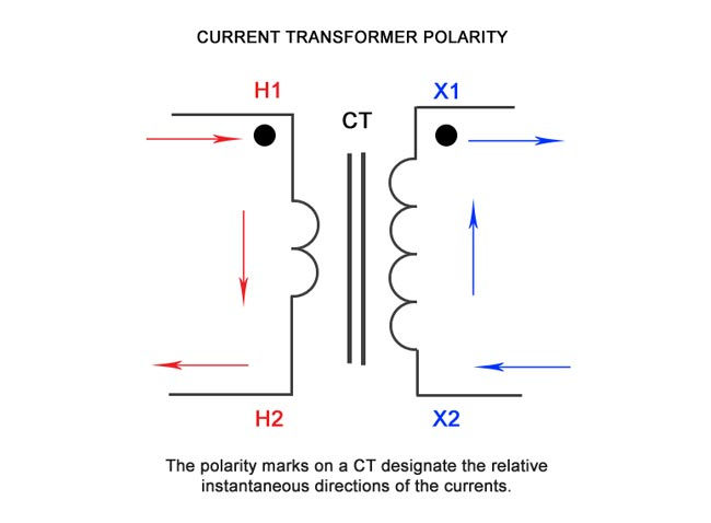
2. Polarity Test
The polarity of a CT is determined by the direction in which the coils are wound around the transformer core (clockwise or counterclockwise) and by how the leads are brought out of the CT case. All current transformers are subtractive polarity and should have the following designations to visually identify the direction of current flow:
H1 - primary current, line facing direction
H2 – primary current, load facing direction
X1 - secondary current
3. Excitation (Saturation) Test


When a CT is "saturated", the magnetic path inside the CT operates like a short circuit on the transmission line. Almost all of the energy supplied by the primary winding is shunted away from the secondary winding and is used create a magnetic field inside the CT.
Saturation testing for a current transformer identifies the rated knee point against IEEE or IEC standards, the point at which the transformer is no longer able to output current in proportion to its specified ratio.
Excitation tests are performed by applying an AC voltage to the secondary winding of the CT and increasing the voltage in steps until the CT is in saturation. The "Knee" point is determined by observing a small voltage increase causing a large increase in current.
The test voltage is slowly decreased to zero to de‐magnetize the CT. The test results are plotted on a logarithmic (log‐log) graph and evaluated based on the transition period between normal operation and saturation.
IEEE defines the saturation as "the point where the tangent is at 45 degrees to the secondary exciting amperes". Also known as "knee" point. This test verifies that the CT is of correct accuracy rating, has no shorted turns in the CT and no short circuits are present in the primary or secondary windings of the CT under test.
4. Insulation Resistance Test

We need a handy Insulation Tester ( 0 to 5KV ) for conducting the IR testing on CT Secondary. The insulation between the current transformer windings and windings to ground should be checked for dielectric strength while performing a comprehensive CT test.
Three tests are performed to determine the condition of the insulation of the CT under test:
Primary to secondary: Checks the condition of the insulation between high to low.
Primary to ground: Checks the condition of the insulation between high to ground.
Secondary to ground: Checks the condition of the insulation between low to ground.
Insulation resistance readings should remain fairly constant over a period of time. A sharp dip in trending of insulation resistance values point towards insulation degradation and further investigation is required to diagnose the problem.
Insulation tests on current transformers rated 600V or less are usually performed at 1000VDC. for Current transformers with rated voltage >1000 to 5000V we need an IR tester with voltage 5000V DC , short the primary winding of the CT under test by connecting H1 and H2, then short the secondary winding of the CT under test by connecting X1 and X2-X5.
Remove the neutral ground and isolate the CT from any associated burden. After the windings are shorted, the CT will be a three terminal specimen.
Insulation resistance test values for CT's should be compared with similar readings obtained with previous tests. Any large deviation in historical readings should call for further investigation.
5. Winding Resistance Test (@ 75'C )

The DC winding resistance measurement is an important measurement in accessing the true condition, state and accuracy of a CT. Winding resistance in a CT will change over a period of time depending on the specimen age, use, external conditions and loading effect.
Few advance CT/PT Analyzers have internal temperature sensor which measures the ambient temperature during testing. The Winding resistance result is measured at ambient temperature . Same result is calculated @75'C automatically.
It is recommended to measure DC winding resistance periodically on a single tap or multi tap CT and trend the values. A high precision low resistance measurement circuit is required to obtain this small winding resistance.
The winding resistance of a current transformer is found by dividing the voltage drop across the winding (measured from dc milli voltmeter) with the applied dc current through the winding. The CT should be demagnetized after the completion of winding resistance test.
6. Burden Test
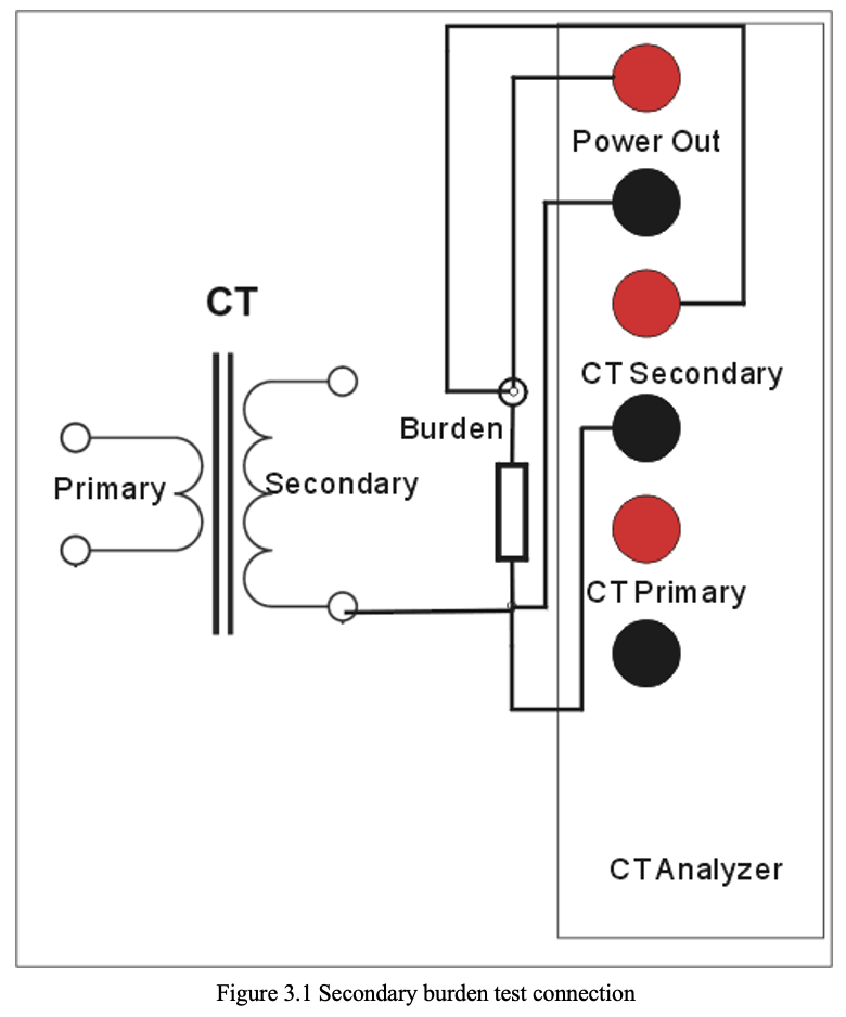
The burden of a current transformer can be defined as the total impedance in ohms on the secondary output terminals. The total burden is a combination of impedance offered by watt-hour meter coils, relay current coils, contact resistance, terminal blocks, wire resistance and test switches used in the secondary loop.
Each current transformer has a secondary burden when connected in a relay or metering circuit. CT's ar
e expected to provide the secondary output current based upon their accuracy class.
If a current transformer is not properly sized based upon secondary loop burden, it may result in a decrease in CT secondary current. Burden testing is important to verify that CT is supplying current to a circuit that does not exceed its burden rating.
The burden test is also useful in ensuring that the CTs are:
Not energized with shorting devices installed (if used for metering or protection)
Not left with an open circuit when not used
Connected with a
single ground point
All connections are tight


Comments