

Why Does a Transformer Differential Relay Trip Without an Internal Fault?
KPM ENGINEERING SOLUTIONS · TECHNICAL NOTE
14 causes of false 87T trips — commissioning-stage errors and in-service effects — and the test that proves or rules out each one
Part A — Commissioning stage | Part B — In service |
A1 Wrong CT ratio or ratio compensation | B1 Magnetizing inrush |
A2 Reversed CT polarity or crossed phases | B2 CT saturation during an external fault |
A3 Wrong vector-group compensation | B3 CT remanence |
A4 Zero-sequence current not eliminated | B4 Overexcitation |
A5 CT secondary circuit left wrong after testing | B5 On-load tap changer position |
A6 Differential settings that do not suit the application | B6 CT circuits that deteriorate in service |
A7 Wrong trip logic or output mapping | B7 Relay measurement-channel faults |
Contents
Introduction
How transformer differential protection (87T) works
Part A — Commissioning-stage causes
A1 Wrong CT ratio or ratio compensation
A2 Reversed CT polarity or crossed phases
A3 Wrong vector-group compensation
A4 Zero-sequence current not eliminated
A5 CT secondary circuit left wrong after testing
A6 Differential settings that do not suit the application
A7 Wrong trip logic or output mapping
Part B — In-service causes
B1 Magnetizing inrush
B2 CT saturation during an external fault
B3 CT remanence
B4 Overexcitation
B5 On-load tap changer position
B6 CT secondary circuits that deteriorate in service
B7 Relay hardware or measurement-channel faults
How to tell which cause it was
Troubleshooting workflow after an unwanted 87T trip
Which instrument proves what
Frequently asked questions
Conclusion
Introduction
A transformer differential relay trips on the differential current it calculates, not on whether the transformer is actually faulty. If the currents it receives from the HV and LV current transformers (CTs) do not balance after compensation, it can trip a perfectly healthy transformer.
Those false trips come from two very different places:
• Commissioning-stage causes — wrong settings, wrong CT data, wrong wiring. Human or documentation errors, usually caught (or missed) before or at first energization.
• In-service causes — physics, not people. Magnetizing inrush, CT saturation during an external fault, overexcitation and tap-changer mismatch can all trip a correctly set, correctly wired relay.

Figure 1. The two families of false differential trips.
This note walks through both families, shows a worked example for each major cause, and explains which test proves or rules it out. Knowing which family a trip belongs to tells you where to start looking — and stops engineers from simply raising the pickup setting until the trips go away.
The key principle: a differential relay responds to the differential quantity it calculates. Any error between the primary currents and that calculation — in the CT, the wiring, the settings or the physics — looks to the relay exactly like an internal fault.
How transformer differential protection (87T) works
The relay compares the current entering the transformer with the current leaving it. CTs on the HV and LV sides feed the relay, which scales each current for the transformer ratio and the CT ratios, corrects for the vector-group phase shift, and then compares them.

Figure 2. Through-current balances; an internal fault does not.
In simplified form, using compensated currents I₁′ and I₂′ with both CTs referenced into the protected zone:
I_diff = | I₁′ - I₂′ |
I_bias = ( | I₁′ | + | I₂′ | ) / 2
For a healthy transformer carrying load or a through-fault, current flows in on one side and out on the other, so the two compensated vectors cancel and I_diff is close to zero. For an internal fault, both sides feed the fault and I_diff becomes large. Exact formulas and sign conventions differ between relay manufacturers.
Why the bias (restraint) characteristic matters. Real CTs are never perfectly matched, and a tap changer shifts the ratio. A percentage-biased relay therefore trips only when I_diff exceeds a threshold that rises with the through-current: a minimum pickup at low current, then one or two slopes. Heavy through-current earns more tolerance.

Figure 3. Bias characteristic with trip and restrain zones. Coloured points are the worked examples in this note.
This gives three things that must all be right for the relay to stay stable:
1. The data — transformer MVA, voltages, vector group and both CT ratios entered correctly.
2. The measurement chain — CTs with the right ratio, polarity and performance, wired to the right relay inputs.
3. The characteristic — pickup, slopes and harmonic restraint set to suit the transformer and the CTs.
The first two are verified at the CTs with a CT PT analyzer; the third, and the relay's response to all of it, with a secondary-injection relay test kit. The rest of this note is a list of the ways each one goes wrong.
Part A — Commissioning-stage causes
These causes are all errors of data, wiring or configuration. The transformer, CTs and relay are healthy; something between them was entered or connected wrongly. They usually show up at first load, at the first through-fault, or right after a relay replacement or maintenance outage.
A1. Wrong CT ratio or ratio compensation
The relay must scale both sides to a common base using the transformer rating and both CT ratios. If any of those numbers is wrong, the two sides never balance.
Worked example — 40 MVA, 132/33 kV transformer
Quantity | HV side (132 kV) | LV side (33 kV) |
Rated line current | 175 A | 700 A |
CT ratio installed | 200/1 | 800/1 |
CT secondary current at rated load | 0.875 A | 0.875 A |
Relay's view if LV ratio is entered as 600/1 | 1.00 pu | 0.75 pu |
With the wrong LV ratio, the relay calculates 0.25 pu differential current at rated load. That is the same order as a typical minimum pickup, so the relay may sit quietly at light load and then trip on a heavy-load day or on the first external fault. The numbers are illustrative; the exact result depends on the relay's reference convention and settings.
Common sources of the error: wrong CT ratio typed in, a multi-ratio CT wired on the wrong tap, the metering core used instead of the protection core, wrong MVA or rated voltage, or settings lost during a relay swap.
How to prove it: measure the actual ratio and the tap in use on every CT with a CT PT analyzer, compare against the setting sheet, then inject the calculated balanced currents on both sides with a relay test kit and confirm the relay reads near-zero differential.
A2. Reversed CT polarity or crossed phases
Polarity tells the relay which way current is flowing. Reverse S1 and S2 on one side and the relay sees current flowing into the zone from both sides, which is exactly what an internal fault looks like.
Wiring condition | Relay sees I_diff at 1 pu through-current |
Correct polarity, correct phases | ≈ 0 pu |
One side's CT polarity reversed | 2.0 pu (currents add instead of cancel) |
Two phases swapped on one side (120° error) | ≈ 1.7 pu |
A reversed CT will usually trip the transformer as soon as load reaches a fraction of rating — even 20 % load gives 0.4 pu. Causes include swapped S1/S2, a CT star point formed on the wrong side, phase A/B/C landed on the wrong relay inputs, and wiring changed during maintenance without a re-check.
How to prove it: a CT polarity test at each CT (a CT PT analyzer reports polarity with every ratio test), phase identification through to the relay terminals, and a through-current stability check before the transformer is put into service.
A3. Wrong vector-group compensation
A Dyn11 transformer shifts the LV currents by 30° relative to HV. The relay has to undo that shift before comparing. Enter the wrong vector group and the phases no longer line up, even with perfect ratios and polarity.
The resulting differential current for an angle error θ is 2 × sin(θ/2) per unit of through-current:
Actual group | Entered in relay | Angle error | I_diff at 1 pu load |
Dyn11 | YNyn0 | 30° | 0.52 pu |
Dyn11 | Dyn1 | 60° | 1.0 pu |
Dyn11 | Dyn5 | 180° | 2.0 pu |

Figure 4. Correct wiring, reversed CT polarity and a 30° vector-group error, as phasors.
A related trap is double compensation: an older scheme with delta-connected CTs or interposing CTs is retrofitted with a numerical relay that also compensates internally. The shift is then corrected twice.
How to prove it: read the vector group from the nameplate, then use a three-phase relay test kit with enough current outputs to inject both windings at once at the correct angles. Testing magnitudes alone will not catch an angle error.

Figure 5. Six-current output panel of a KPM relay test kit (from the KRT manual). Group 1 (IA, IB, IC) feeds the relay's HV winding inputs and Group 2 (Ia, Ib, Ic) the LV inputs, so both windings are injected together with independent angles.
A4. Zero-sequence current not eliminated
On a Dyn11 transformer with an earthed LV neutral, an external earth fault on the LV side drives zero-sequence current through the LV CTs. That current circulates inside the HV delta and never reaches the HV CTs, so the relay sees an imbalance.
Relays remove it with a zero-sequence elimination (or filtering) setting on the earthed winding. If that is disabled, or the earthing arrangement is entered wrongly, the relay is stable on load and three-phase faults but trips on the first external earth fault. That can be months after commissioning, which is why this setting error is often mistaken for an in-service problem. An earthing transformer inside the protected zone needs the same attention.
How to prove it: simulate an external single-phase-to-earth fault on the star side with a relay test kit and confirm the relay stays stable.
A5. CT secondary circuit left wrong after testing
The relay is only as good as the copper between it and the CTs. Commissioning-stage faults in that circuit include:
• CT shorting links left closed, or a test block left in the test position — the relay sees zero current from that side, so full load current becomes differential current.
• CT secondary earthed at more than one point, letting circulating currents into the measurement.
• The protection core and the metering core swapped. A metering core is designed to saturate early, so it collapses on the first heavy through-fault.
Safety: never open-circuit a CT secondary while the primary is energized. The secondary voltage can rise to dangerous levels and damage the CT.
A6. Differential settings that do not suit the application
Even with correct data and wiring, the characteristic itself can be too sensitive or switch off a needed security feature.
Setting | What goes wrong |
Minimum differential pickup | Set too low to cover CT mismatch and tap range |
Bias slope 1 / slope 2 | Too little restraint for CT errors at high through-fault current |
2nd harmonic restraint | Disabled, or set too high to catch the inrush of the actual transformer |
Cross-blocking | Disabled, so one phase with low harmonic content trips during inrush |
5th harmonic restraint | Disabled where overexcitation is expected |
Unrestrained (high-set) element | Threshold below the transformer's peak inrush current |
Settings must come from a calculation using the transformer data, the CT data, the system fault levels and the relay manufacturer's application guide. Copying generic values from another substation is a common root cause.
How to prove it: a relay test kit tests the pickup, plots the bias characteristic point by point, and checks harmonic blocking by injecting a fundamental with a chosen percentage of 2nd or 5th harmonic.
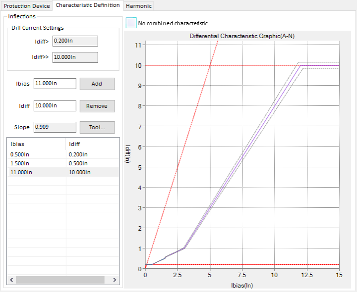
Figure 6. Differential characteristic defined in the KPM relay test software (from the KRT manual): Idiff> 0.2 In, inflection points and slopes entered, ready to test the relay point by point against it.
A7. Wrong trip logic or output mapping
Sometimes the differential element never operated at all. Another function — restricted earth fault, overcurrent, a Buchholz or pressure-relief input — is mapped to the same output contact or the same “87T” LED. The event record looks like a differential trip until the logic is read.
How to prove it: check the programmable logic against the approved scheme, then operate each function with a relay test kit and confirm which output and which LED respond.
Part B — In-service causes
These causes have nothing to do with a wrong setting or a crossed wire. The relay is set and connected correctly, yet the currents reaching it genuinely do not balance for a moment. They are harder to diagnose because a commissioning check will pass every time.
B1. Magnetizing inrush
What happens. When a transformer is switched on, the core has to build up its magnetic flux. Depending on the point on the voltage wave at closing and the flux left in the core, the core can saturate and draw a current several times rated — sometimes more than ten times for smaller units — decaying over seconds.
Why the relay can trip. Inrush flows only on the energized side. There is nothing matching it on the other side, so all of it is differential current. Relays block on inrush by measuring its 2nd harmonic content, which is normally high.

Figure 7. Illustrative inrush current compared with rated load current.
A correctly set relay can still trip when:
• one phase carries inrush with unusually low 2nd harmonic content, which modern low-loss core steels can produce, and cross-blocking is not used;
• sympathetic inrush occurs — energizing a second transformer in parallel drives the already-energized one into inrush, with a slower decay and lower harmonic content;
• recovery inrush occurs — when an external fault is cleared, the voltage recovers suddenly and re-magnetizes the core.
Typical evidence: the trip comes within the first cycles after the breaker closes, or right after a nearby fault is cleared. The recorded current is one-sided and peaky, with gaps.
B2. CT saturation during an external fault
This is the most important in-service cause because it trips a transformer for a fault that is not even in the transformer.
What happens. A CT reproduces the primary current faithfully only until its core saturates. A heavy external fault — especially one with a large DC offset from a high X/R ratio — can drive the core into saturation within a few milliseconds. The secondary current then collapses for part of each cycle.
Why the relay can trip. If the HV and LV CTs saturate differently, the relay sees two unequal currents and calculates a false differential. Different saturation is common, because the two sides usually have different CTs:
• different accuracy classes and knee-point voltages;
• different secondary burdens, especially with long cable runs from the yard;
• different remanent flux left in each core (see B3);
• a much higher fault current through one set of CTs than the other.

Figure 8. Illustrative external fault: the healthy CT follows the primary, the saturating CT loses current, and the gap appears as differential current.
Moment | HV compensated current | LV compensated current | Apparent I_diff |
Before saturation | 8 A | 8 A | 0 A |
After the LV CT saturates | 8 A | 4 A | 4 A |
The illustrative 4 A differential is two-thirds of the 6 A bias current — steeper than most second-slope settings. The bias characteristic and the relay's CT-saturation detector are there to ride through this, but they only work if the CTs have enough margin.
How to prove it: measure the excitation curve and knee-point voltage of the CTs on both sides, plus winding resistance and the connected burden, and check them against the fault level the CTs must carry. A CT PT analyzer does this in one connection; low-frequency excitation testing lets a portable instrument reach high knee-point voltages. Then review the disturbance record for clipped or flattened waveforms on one side.
A relay test kit injecting clean sine waves cannot reproduce physical saturation of the installed CT. To test the relay's response to saturation, play back a recorded or simulated distorted waveform — the TransPlay module in the KPM relay test software is built for this (see Figure 10).
B3. CT remanence
A closed-core CT can keep a large part of its saturation flux after the current stops. The next fault then starts from a partly magnetized core and saturates far sooner than its knee point suggests.
Remanence is left behind by an earlier fault with a DC offset — and by DC tests during commissioning or maintenance: winding-resistance measurements and the battery “flick” polarity check. This is why a CT tested with DC should be demagnetized before the transformer returns to service. Where through-fault stability is critical, specifying low-remanence CT classes removes the risk at source.
B4. Overexcitation
What happens. Core flux is proportional to voltage divided by frequency (V/f). An overvoltage, a low frequency, or both — a generator transformer during start-up or after a load rejection, or an islanded network — push the core towards saturation.
Why the relay can trip. The magnetizing current rises steeply and flows only on the supply side, so it appears as differential current. It is rich in 5th harmonic, which is what 5th harmonic restraint looks for.
What to do: keep V/f within the transformer's permitted limit, enable 5th harmonic restraint where overexcitation is credible, and provide a dedicated overexcitation (V/f, 24) function. That function — not the differential relay — should decide whether an overexcited transformer is tripped.
B5. On-load tap changer position
What happens. The tap changer alters the transformer's turns ratio to regulate voltage. The relay's ratio compensation is set for one tap, usually nominal or mid-tap.
Why the relay can trip. At the extreme of a ±10 % tap range, the actual ratio differs from the set ratio by about 10 %. That appears as roughly 0.1 pu differential at rated load, and proportionally more during overloads and through-faults. If the pickup and slope do not cover the full tap range plus CT errors, the relay trips at the extreme taps.
How to prove it: confirm the setting calculation covers the full tap range, and use a relay test kit to inject the current mismatch that corresponds to the highest and lowest taps at rated and fault current.
B6. CT secondary circuits that deteriorate in service
A circuit that was perfect at commissioning can degrade: terminals loosen with vibration and thermal cycling, links corrode, moisture enters marshalling boxes, cables are damaged. The results are intermittent open circuits, high-resistance joints that add burden and make CTs saturate earlier, and leakage between circuits.
Typical evidence: a trip at ordinary load with no system event, or a differential current that comes and goes. A burden or loop-resistance check, insulation resistance of the secondary wiring, and a thermal scan of the terminal blocks usually find it.
B7. Relay hardware or measurement-channel faults
An analogue input, its internal CT, or the conversion circuit can drift or fail. The relay then calculates a current that is not flowing. Most numerical relays raise a self-supervision alarm, but not every fault is caught.
How to prove it: compare the relay's measured values on every channel against known currents injected by a relay test kit. A channel that reads wrong under clean injection is the relay, not the system.
How to tell which cause it was
When the trip happened is the fastest clue. Read it from the relay's event log and disturbance record before touching any setting.
When or how the trip happened | Most likely causes | Check first |
At first load after commissioning or a relay swap | A1 ratio, A2 polarity, A3 vector group | Setting sheet vs nameplates; CT ratio and polarity |
Differential current present at steady load, rising with load | A1, A2, A3, B5 tap position | Relay's measured winding currents and angles |
Within cycles of the breaker closing | B1 inrush, A6 harmonic settings | Harmonic content in the disturbance record |
When a parallel transformer was switched in | B1 sympathetic inrush | Switching log and waveform |
During a heavy fault outside the zone | B2 saturation, B3 remanence, A6 slope | Clipped waveform on one side; CT knee points |
During an external earth fault only | A4 zero-sequence elimination | Earthing arrangement setting |
During high voltage or low frequency | B4 overexcitation | V/f at the time; 5th harmonic |
Only at extreme tap positions | B5 tap changer | Tap position at the time of trip |
At normal load, no system event, intermittent | B6 wiring deterioration, B7 relay channel | Terminal tightness; channel accuracy by injection |
Event says “87T” but differential quantities were small | A7 trip logic | Output and LED mapping |
These are clues, not proof. A genuine internal fault — especially an inter-turn fault that produces only a small differential current — must be ruled out before any trip is called a false trip.
Troubleshooting workflow after an unwanted 87T trip
Work from evidence to cause, in this order. Raising the pickup or slope before step 6 hides the problem instead of fixing it.
1. Read the trip record. Note the operated element, phase, differential and bias currents, harmonic levels and the sequence of events. Was it energization, steady load or an external fault?
2. Rule out a real transformer fault. Check Buchholz, pressure relief, oil temperature and gas alarms. Follow the utility's procedure; a dissolved gas analysis may be needed before re-energizing.
3. Verify the CTs. Ratio, tap in use, polarity, excitation curve and knee point, winding resistance and connected burden on both sides — with a CT PT analyzer.
4. Verify the CT secondary circuit. Phase identification to the relay terminals, star point and single earth point, shorting links and test blocks, terminal tightness.
5. Verify the relay configuration. Transformer MVA, voltages, vector group, CT ratios, zero-sequence elimination and every differential setting against the approved setting sheet.
6. Test the relay by secondary injection. Pickup, bias characteristic, 2nd and 5th harmonic blocking, vector-group stability with both windings injected at the correct angles, and the trip outputs — with a relay test kit.
7. Investigate transients if needed. If inrush or CT saturation is suspected, analyse the recorded waveforms, and play them back into the relay where the test set supports it.
8. Restore and record. Put the scheme back in service only after the cause is found and the checks are complete. Record what was found so the next engineer starts ahead.
Safety note: transformer differential is critical protection. Never disable or bypass it to stop recurring trips. Follow approved isolation, CT-secondary and permit-to-work procedures, and obtain authorization before changing protection settings.
Right instrument brings right insight.
No single instrument covers every cause. A relay test kit proves the relay; a CT analyzer proves the CTs. A differential scheme needs both, because a perfectly tested relay will still trip if its CTs are wrong.

Figure 9. What each instrument verifies in a transformer differential scheme.
Check | Rules out | Instrument |
CT ratio and tap in use | A1 | CT PT analyzer |
CT polarity | A2 | CT PT analyzer |
Excitation curve, knee point, winding resistance | B2 saturation, A5 wrong core | CT PT analyzer |
Secondary burden | B2, B6 | CT PT analyzer |
Demagnetization after DC tests | B3 remanence | CT PT analyzer, where the instrument offers it |
Pickup and bias characteristic | A6 | Relay test kit |
Vector-group and zero-sequence stability | A3, A4 | Three-phase relay test kit, both windings injected |
2nd and 5th harmonic restraint | B1, B4, A6 | Relay test kit, Harmonic module |
Replay of recorded inrush or saturation waveforms | B1, B2 | Relay test kit, TransPlay module |
Tap-range mismatch | B5 | Relay test kit |
Channel accuracy | B7 | Relay test kit |
Output and LED mapping | A7 | Relay test kit |
KPM CT PT Analyzer
The KPM CT PT Analyzer measures ratio, polarity, excitation curve and knee point, winding resistance and burden from a single connection, and evaluates the CT against its accuracy class. It complies with IEC 61869, the current instrument-transformer standard, while still supporting the older IEC 60044 references found on many nameplates and specifications. Its low-frequency excitation method lets a portable instrument test CTs with high knee-point voltages — the protection-class CTs that differential schemes depend on.
KPM relay test kits
KPM relay test kits are secondary-injection test sets for numerical and static relays. For transformer differential work, choose a model with enough current outputs to inject the HV and LV windings at the same time with independent angles; that is what proves vector-group compensation and stability. KPM's range includes three-phase and six-current models, including IEC 61850-capable sets for digital substations.

Figure 10. KPM Relay Test System software (from the KRT manual). The Harmonic module tests 2nd and 5th harmonic restraint; TransPlay replays recorded transient waveforms such as inrush or CT saturation into the relay.
Both come with KPM's application support: our engineers help set up the test plan for your relay and transformer, not just the instrument.
Frequently asked questions
1) Why does a differential relay trip when the transformer is energized?
Magnetizing inrush flows only on the energized side, so the relay sees it as differential current. A correctly set relay blocks it using the 2nd harmonic content of the inrush. Trips usually mean harmonic restraint is disabled or set too high, cross-blocking is off, or the inrush has unusually low harmonic content.
2) Can CT saturation trip a transformer differential relay for an external fault?
Yes. If the HV and LV CTs saturate by different amounts during a heavy through-fault, the relay sees unequal currents. Checking the knee-point voltage of both CT sets with a CT PT analyzer, against the fault level they must carry, is the way to find out before it happens.
3) How do I check differential relay stability during commissioning?
Inject both windings at once with a three-phase relay test kit, at the magnitudes and angles a through-current would produce for the transformer's vector group. The relay should read near-zero differential. Then confirm the CT ratio and polarity at the CTs themselves.
4) What is the difference between a commissioning error and an in-service false trip?
A commissioning error is a wrong setting, wrong CT data or a wiring mistake; it is present from day one and is found by checking. An in-service false trip comes from a physical effect such as inrush, CT saturation or overexcitation, and can occur on a correctly set and wired relay.
5) Should I increase the differential pickup to stop nuisance trips?
Not before the cause is found. A higher pickup reduces sensitivity to real internal faults, especially inter-turn faults, and often leaves the actual problem — a wrong ratio, a reversed CT or an undersized CT — in place.
Conclusion
A transformer differential relay trips without an internal fault for one of two reasons. Either something was entered or wired wrongly — CT ratio, polarity, vector group, zero-sequence handling, settings or logic — or a physical effect briefly unbalanced the currents: inrush, CT saturation, remanence, overexcitation, tap position, a deteriorating circuit or a failing relay channel.
The first family is found by checking, at the CTs and at the relay. The second is prevented by specifying CTs with enough margin, setting the relay's restraint functions for the real transformer, and keeping the measurement chain healthy. In both cases the fix is to find the cause, not to desensitize the protection.
Talk to a KPM application engineer. Commissioning a transformer differential scheme, or chasing a trip you can't explain? KPM's engineers will help you plan the CT and relay tests for your transformer and choose the right CT PT analyzer or relay test kit for the job. Call 0124 4001088 or visit www.kpmtek.com.


Comments