
KPM Tan Delta 12
TD12

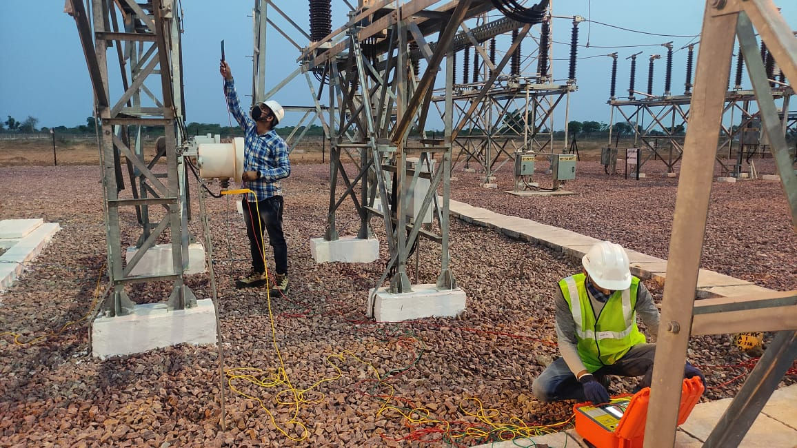
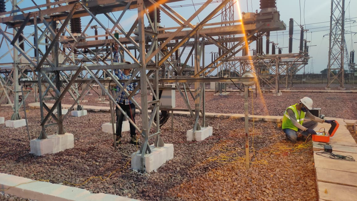
KPM-TD12 Automatic 12KV Capacitance & Dissipation Factor Test Set is used to measure the dissipation factor (PF) of insulating materials in heavy interference sites such as power plants or power substations. It can also be used in laboratory for high accuracy capacitance and dissipation measurement.
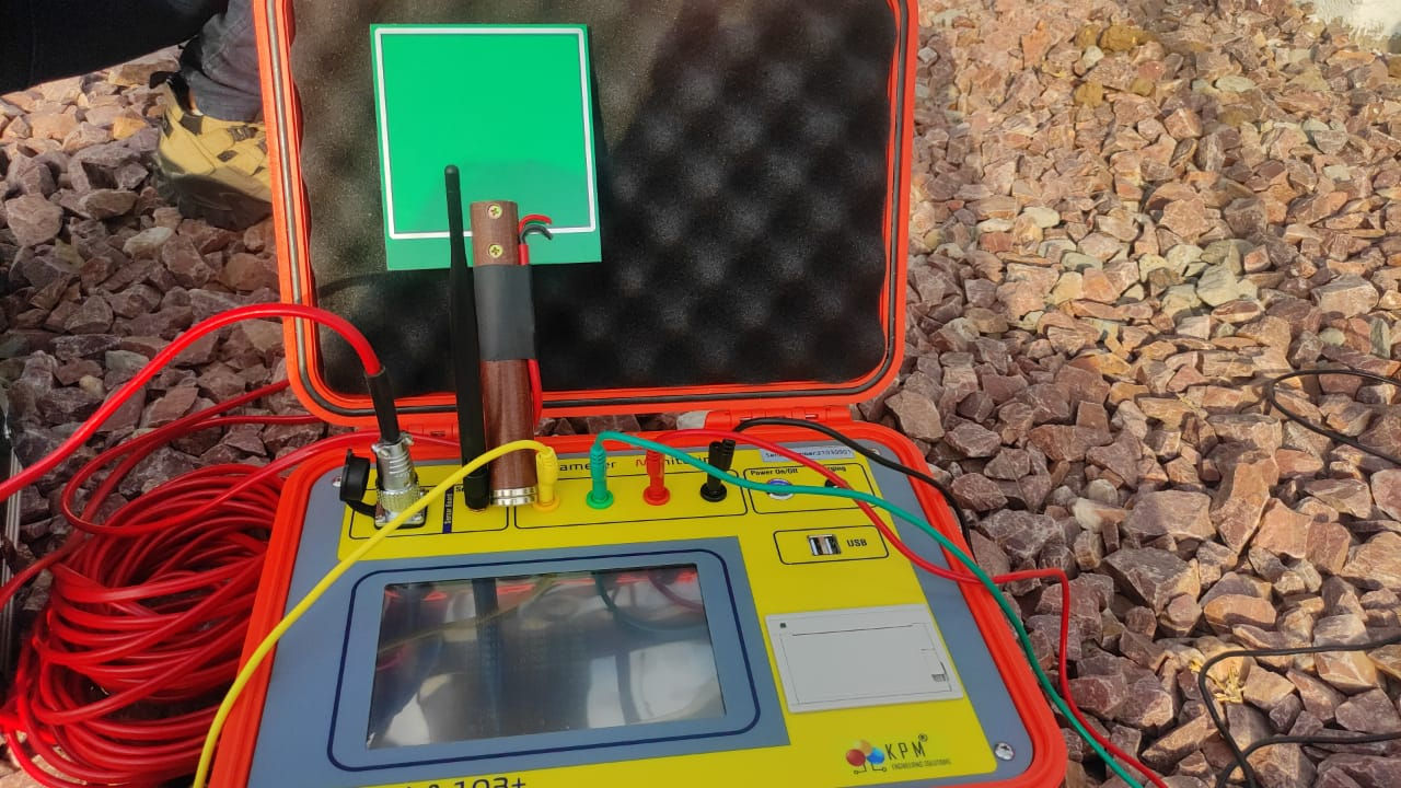
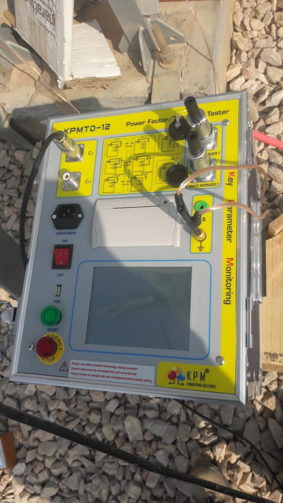
The test set is all in one unit which includes precision digital bridge, power unit, internal reference capacitor (CN), booster transformer and other electronic circuits. When started, it runs automatically and display the results on LCD. Micro printer can be used to print the results automatically.
Features :
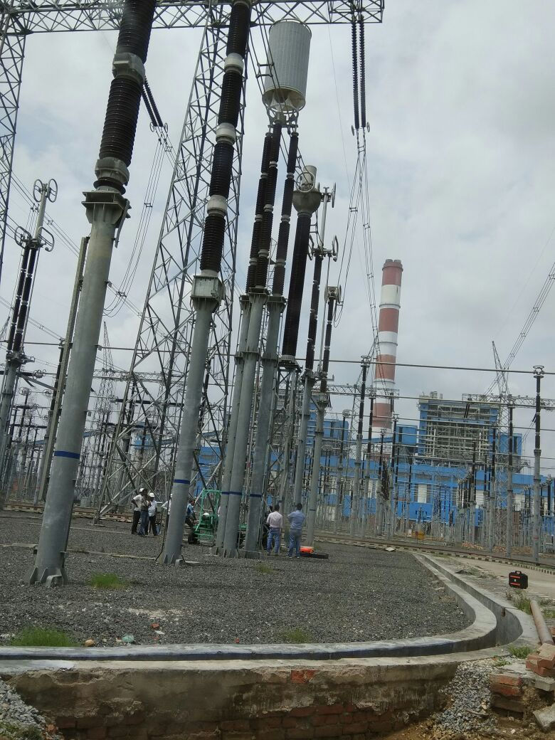
High stability in noisy environment of EHV S/S ( upto 765 KV)
Simple operation, the instrument is equipped with a high-end full touch LCD screen, super touch interface, and each process is very clear. Operators can use it without additional professional training.
Mass storage data : The instrument is equipped with a calendar chip and large capacity memory. The test results can be stored in chronological order. Users can view historical data at any time and print it out.
Multiple test modes : The instrument can be tested by high pressure, high voltage, standard, positive connection method, reverse connection method, self excitation method and other methods.
CVT test step in place : The instrument can also test the full sealed CVT (capacitor voltage transformer) C1, C2 dielectric loss and capacitance, to achieve the C1, C2 simultaneous test.
Do not dismantle the high-voltage lead measurement CVT : The instrument can accurately measure the dielectric loss and capacitance of CVT without dismantling the CVT high voltage lead.
CVT reverse shield method for measuring C0 : The instrument can be used to measure the dielectric loss and capacitance value of C0 on the upper end of CVT.
High speed sampling signal : The inverter and sampling circuit of the instrument are all controlled by digital, and the output voltage is adjustable continuously.
Multi protection security : The instrument has many protection measures, such as input voltage fluctuation, output short circuit, over voltage, over current and temperature.








Tan delta testing — frequently asked que
- 01Insulation is never a perfect capacitor. Electrically it behaves as a capacitance with a resistance in parallel across it, and tan delta measures the ratio between the currents those two elements draw. Apply AC voltage to ideal insulation and it draws only capacitive current, leading the voltage by exactly 90°. Real insulation has a finite parallel resistance as well, so it also draws a small resistive current in phase with the voltage. The total current therefore falls short of 90° by an angle δ — the loss angle — and tan delta is simply the ratio of those two components: tanδ = IR / IC.A reading of 0.3% means the resistive current is three parts in a thousand of the capacitive current. What makes this the right quantity to measure is that it describes the material rather than the specimen: tanδ = 1/(ωRC), and for a given dielectric the product RC depends only on resistivity and permittivity, so the specimen's size and shape cancel out. As insulation absorbs moisture, becomes contaminated or ages, its parallel resistance falls while its capacitance changes very little — so the ratio rises.
- 02They are closely related but not identical. tanδ is the tangent of the dielectric loss angle δ. Power factor is cos θ, where θ is the phase angle between voltage and current, and δ + θ = 90°. Dissipation factor is simply another name for tan delta. At the low loss values typical of healthy high-voltage insulation the two are numerically almost identical, which is why the terms get used interchangeably in the field and why most instruments display both rather than arguing the point.
- 03They answer different questions. An insulation resistance test applies DC and reports surface leakage and gross contamination, and its value depends on the size and shape of the specimen, which makes readings awkward to compare between different assets — where tan delta, being a ratio, does not. A tan delta test applies AC at or near service stress and reports on the bulk condition of the dielectric — moisture ingress, ageing of the oil-paper system, voids. A bushing or current transformer can pass an IR test comfortably and still show a tan delta trend that says it is deteriorating. In practice the two are sequential rather than alternative: an insulation test is normally carried out first, both as a condition check and as a precaution before AC test voltage is applied.
- 04A rising value means the insulation is dissipating more energy due to resistive path than it previously did — typically from moisture ingress, contamination, ageing, or voids developing within the dielectric. Because the absolute figure depends on equipment type, design, insulation system and temperature, the useful signal is normally the trend against that asset's own history and the comparison between the three phases of the same unit, rather than the reading in isolation. A step change in capacitance measured at the same time is a stronger indicator still.
- 05Capacitance is measured at the same time and reflects the geometry of the insulation rather than its quality. In a condenser-graded bushing, a step increase in capacitance indicates that one or more capacitive layers have punctured and shorted out — a failure mode tan delta alone may not flag dramatically. Catching it depends on capacitance accuracy rather than on tan delta accuracy, which is why a kit intended for bushing work needs a credible figure for both.
- 06Power transformers (winding-to-winding and winding-to-earth), condenser-graded bushings, current transformers, potential transformers, capacitor voltage transformers, surge arresters, capacitors and rotating machine insulation. In a typical substation maintenance schedule, transformer bushings and instrument transformers account for most of the work, because they are the assets where a developing dielectric fault gives little other warning before it fails.
- 07No. It is a diagnostic test performed at or below the equipment's normal operating stress, not a withstand test, so it does not deliberately stress insulation towards failure the way a hipot or applied-voltage test does. That is precisely what makes it suitable for routine condition monitoring — the test can be repeated on the same asset year after year to build a trend without consuming insulation life each time.
- 08They find different things. Tan delta reports a bulk, averaged property of the whole dielectric, so it is good at diffuse deterioration — moisture, ageing, general contamination — and poor at pinpointing a single localised defect. Partial discharge testing detects discrete discharge activity and is far better at finding a specific void or defect, but says little about overall condition. Most maintenance programmes use tan delta as the routine screening test because it is quick and repeatable, and reach for PD when a result needs investigating.
- 09Routine testing on instrument transformers, bushings and transformer windings is commonly performed at 10 kV, with equipment rated below that tested at its own rated line-to-earth voltage. That sets the practical requirement: at least 10 kV with some headroom above it, and genuinely fine adjustment (500V min ) at the low end for lower-rated apparatus — a kit that steps in coarse increments cannot sit neatly on the rated voltage of a small CT.
- 10Because the current the kit must supply rises with both capacitance and voltage. The charging current of a capacitive specimen is I = 2πfCV, so doubling the test voltage doubles the current demand for the same specimen, and a portable source has a finite output. This is a power limit, not a measurement limit. It has a practical consequence when reading datasheets: a capacitance range quoted as a single headline figure tells you almost nothing, because that figure is only achievable at the lowest test voltage. The useful form is a ceiling stated at each voltage — and a large specimen is then tested at a lower voltage rather than refused.
- 11Accuracy is normally quoted in two terms — a percentage of reading plus a fixed floor, written as ±(reading × a% + b) — and which term dominates depends entirely on what you are measuring. On healthy insulation reading a few tenths of a percent, the percentage term is tiny and the fixed floor is essentially the whole error. That makes the fixed term the number to compare between kits, and it is the one most often buried. Resolution is a separate thing and frequently confused with it: resolution is how many digits the display shows, which can easily be more digits than the instrument can justify.
- 12A built-in high-stability standard capacitor means routine testing needs no external reference — one less precision item to transport, calibrate and damage on site, which matters on a testing round that moves between substations. An external standard capacitor input is still worth having, because it is what allows a field accuracy check against a traceable reference and supports high-voltage measurement against an external standard. The practical answer for most field kits is built in, with the external input available when required.
- 13It is the most consequential difference between kits used in energised switchyards. Electric field from adjacent live bays couples into the test leads at power frequency and corrupts the measurement, and the higher the surrounding voltage class the worse it gets. A variable-frequency instrument measures at frequencies deliberately offset either side of mains and filters out the power-frequency component, typically measuring at both offsets and combining the results. Because the interference sits at 50 Hz and the measurement does not, the two are separable. A fixed 50 Hz kit has no mechanism to tell them apart — the interference simply becomes part of the reading, which is worse than a noisy result because it looks plausible.
- 14Yes. A kit with GST, UST and GSTg modes and both polarity options covers power and instrument transformers, condenser bushings, CTs, PTs and CVTs, and with an oil test cell it extends to the dielectric loss of insulating oil. The usual exception is power cable: a cable run of any length presents capacitance far beyond what a power-frequency kit can drive at test voltage, and cable dielectric loss testing is normally done with a dedicated very-low-frequency set at 0.1 Hz instead.
- 15Single-phase mains, and most field instruments tolerate a stated window either side of nominal because site supply is rarely clean. Two things are worth checking before plugging in on an unfamiliar site. First, the absolute maximum input — exceeding it typically causes damage that no warranty covers, so an unstable or unregulated supply should be measured rather than assumed. Second, if the site is running on a generator, the generator's output neutral normally has to be earthed; an unearthed neutral is a common cause of an instrument refusing to start and reporting an earthing fault.
- 16It depends mostly on one design decision: whether the dielectric loss bridge, the test source, the step-up transformer and the standard capacitor are integrated into a single case, or split across two or more units. An integrated kit is heavier as one item but is a single lift and a single set-up; a split design has lighter components but means a second case to carry up a gantry and additional connections to make at every test point. Ask for mass and dimensions of every item that has to reach the test position, not just the main unit. The KPM TD12 has a compact design, with an overall size comparable to a 13-inch MacBook, while weighing only approximately 24 kg.The KPM TD12 Pro is larger in size and offers a higher current capacity. It also comes with a built-in 10 kV insulation resistance (IR) tester, providing additional testing functionality in a single unit.
- 17As a minimum: the instrument, the matched high-voltage and low-voltage test leads, an earthing lead, a mains lead, operating instructions and a certificate of conformity, with a carrying case for the accessories. The test leads deserve more attention than they usually get — an instrument of this class is calibrated together with its supplied leads, and substituting a general-purpose cable can shift the measured result, because the cable's own characteristics become part of the measurement. Replacements should be ordered from the supplier rather than made up locally.
- 18Eight questions that separate datasheets quickly.What is the capacitance ceiling at each test voltage, not just the headline range?What is the fixed term in the accuracy expression, as distinct from the resolution?Is interference rejection by variable frequency or is the kit fixed at power frequency?Are all three of GST, UST and GSTg available, and can both polarities be used?Can a CVT be tested without breaking its high-voltage connection?Is the standard capacitor internal, and can an external one be used for verification?What does the instrument refuse to do when earthing is missing or a specimen is faulty?And who answers the phone when a reading looks wrong at seven in the evening during a shutdown?
- 19They differ in what the measurement includes. UST — ungrounded specimen test — measures only the insulation between two ungrounded terminals and ignores everything connected to earth. 1. Internal voltage - internal standard (CX) - straight polarity method2. Internal voltage - external standard ( CN ) - straight polarity method (must firstly set up the capacity of external standard)3. External voltage - internal standard (CX) - straight polarity method4. External voltage - external standard - straight polarity method (must firstly set up thecapacity of external standard CN ) GST — grounded specimen test — measures everything from the energised terminal to earth. Internal voltage - internal standard - reverse polarity methodInternal voltage - external standard - reverse polarity method (must firstly set up the capacity of external standard)External voltage - internal standard - reverse polarity methodGSTg — grounded specimen test with guard — measures to earth but diverts one current path into a guard circuit so it is excluded from the result. Running them in combination is what lets you resolve individual capacitances rather than only their sums, which is the whole reason a diagnostic set offers more than one mode.GSTg
- 20Straight polarity — also called normal or positive — is used when the specimen’s low-voltage end is free and can be lifted from earth. Test voltage is applied at the high end, and the current is collected from the isolated low end and returned to the instrument’s measuring input. The measuring circuit therefore sits at earth potential, which is both safer and more accurate, and it is the arrangement to use wherever the specimen allows it.Internal voltage - internal standard - straight polarity methodReverse polarity is used when the low end is permanently bonded to earth and cannot be lifted — a great deal of installed apparatus is built that way. The return path then runs through earth, and the measurement has to be taken at the high-voltage end instead. Two consequences follow. The measuring connection sits at test potential, so the work demands more care. And the measurement now sees stray capacitance from the high-voltage lead to earth, which adds into the result — which is why a reverse-polarity test wants the HV lead suspended and clear of ground, and why reverse-polarity readings are generally held to be the less accurate of the two.Internal voltage - internal standard - reverse polarity methodBoth arrangements then divide again, according to where the test voltage comes from and where the reference comes from.A tan delta bridge does not measure the specimen on its own. It compares the current through the specimen against the current through a standard capacitor at the same voltage, and the result is the difference between them. With the instrument’s own source and its own built-in standard that equality is automatic, and it covers the great majority of field work. An external standard is needed in three situations:when an external high-voltage source is being used,when a traceable reference is wanted for an accuracy checkwhen the test voltage is above what the built-in standard is rated for.wo conditions attach to it. Its capacitance value must be entered into the instrument before the test, or every reading is wrong in proportion to the difference. And it must be a genuinely low-loss reference, because the standard’s own dielectric loss enters the result as an error..An external high-voltage source is needed when the test calls for more voltage than the internal source produces, or more current than it can drive into a large capacitive specimen. In that arrangement the instrument stops being the source and works purely as a bridge, and one rule governs the wiring: the external source must energise the specimen and the standard capacitor from the same point. If the two branches see different voltages the comparison is meaningless — and the reading will still look entirely plausible (Straight Polarity Method — internal or external source, against internal or external standard)(Reverse Polarity Method- internal or external source, against internal or external standard)
- 21Because the reference’s own loss lands directly in your answer. A tan delta bridge compares the current through the specimen against the current through a standard capacitor, and reports the difference between them. Whatever dielectric loss the standard has therefore appears in the result as an offset on every reading it is ever used for. That sets a hard requirement. Healthy insulation is being measured at a few tenths of one per cent, so the reference has to sit two or three orders of magnitude below that — loss low enough to be treated as zero. No solid dielectric can do this. Every solid insulating material has measurable loss of its own, and that loss shifts with temperature and humidity and creeps upward as the material ages — the very behaviour the instrument exists to detect. A reference built from solid dielectric would be a specimen pretending to be a standard.A gas dielectric has effectively none of it. Compressed nitrogen or SF6 has no polar structure to dissipate energy, so the loss is set by the electrode geometry rather than by a material property. Two further benefits come with it. The capacitance is fixed by the mechanical spacing of rigid electrodes rather than by a material constant, so it is stable over years rather than drifting. And compressing the gas raises its breakdown strength, which lets the electrodes be spaced for high voltage without the capacitor becoming unmanageably large.The practical consequence matters more than the physics. If you ever connect an external reference, it must be a purpose-built gas-filled standard. A power-factor-correction capacitor, a film capacitor or whatever high-voltage unit happens to be on the shelf has loss comparable to or greater than the value you are trying to measure. It will give you readings — plausible ones — that are mostly a measurement of the capacitor you substituted. KPM’s Tan Delta Kits have high quality gas filled capacitors.
- 22An external high-voltage source is used when the test calls for a voltage above what the instrument's internal source produces. An external standard capacitor is used when measuring against a traceable external reference — for an accuracy verification, or for high-voltage measurement against an external standard. One prerequisite applies whenever an external standard is used and is a common source of wrong results: its capacitance value has to be entered into the instrument before the test is run, or every reading is out by whatever the difference happens to be.
- 23With two guarded measurements that between them separate the insulation paths.GSTg ( Chg+Chl)GSTg ( Clg+Clh) For CHG + CHL, the guard is applied to the LV winding and the measurement is taken from the HV winding. For CLG + CLH, the guard is applied to the HV winding and the measurement taken from the LV winding. Adding an ungrounded measurement of the winding-to-winding capacitance lets the individual values be resolved rather than left as sums. The principle to hold on to is simple: whichever winding the guard is applied to is the winding excluded from that measurement.
- 24Three-winding transformer CHG+CHL(shield of high voltage line connected to T winding)Three-winding transformer CTG+CHTLV (shield of high voltage line connected to winding)Three guarded measurements, each excluding a different winding — CHG + CHL guarding the tertiary, CLG + CLT guarding the HV winding, and CTG + CHT guarding the LV winding. The pattern is the same one as for a two-winding unit, applied three times: the guarded winding is the one taken out of the measurement. Getting the guard onto the wrong winding is the most common error in this test and produces a result that looks entirely reasonable, which is what makes it dangerous.
- 25On instruments that include the function, yes — dielectric loss, capacitance, ratio and phase angle can be measured in one visit with one set of connections. For CVT work this is worth more than it first appears, because it removes a separate ratio set from the kit and, more to the point, removes a second round of connecting and disconnecting at height on an asset that is awkward to reach.
- 26
- 27More than the test itself, because the technique is only as good as the baseline it is compared against. Each result needs the test voltage, the frequency, the mode and connection used, the specimen temperature, and the date — a reading recorded without its temperature cannot be meaningfully compared with anything measured later. On-board storage and an export route both matter for this reason: storage keeps the record at the point of test where it cannot be mislaid, and export is what gets it into a trend that survives a change of personnel.
- 28Start with the connections, because that is where most cases end. The measuring lead has to land on a genuinely zero-resistance point on the specimen at both ends — a painted terminal, a loose clamp or a corroded stud is enough to make a reading wander, and the fault is invisible at a glance. Next, check that the supplied test leads are being used: an instrument of this class is calibrated with its own leads, and a substituted cable brings its own characteristics into the measurement. After that, look at shielding and earthing, then at whether interference from nearby energised equipment is reaching the test loop.
- 29Treat it as a protection working rather than a fault. Instruments of this class detect the earth connection and deliberately refuse to raise voltage without a reliable one, which is the behaviour you want. Check the earthing lead back to station earth first, and check it at both ends rather than at the instrument only. If the site is running on a generator, check the generator: an unearthed output neutral is a frequent cause of an earthing prompt and is the one operators rarely think of, because the instrument was working perfectly on mains an hour earlier.
- 30Yes, and in a working substation it is usually the dominant error source. Electric field from adjacent live bays couples into the test loop at power frequency. A variable-frequency instrument handles this by measuring away from power frequency and filtering out the coupled component, which is what makes testing practical with the rest of the yard energised. Good practice helps regardless of instrument: keep test leads off the ground and clear of live conductors, keep the high-voltage lead suspended, terminate shields properly, and keep the loop area as small as the job allows.
- 31A small difference is not unusual, because dielectric loss in some insulation systems is genuinely frequency-dependent. A large divergence is a different signal: it usually means interference rejection is incomplete, and it is a prompt to check connections, shielding and earthing before the result is trusted at all. Treat a wide spread between frequencies as information about the test set-up rather than about the insulation.
- 32Tan delta is strongly temperature-dependent, so results are normally corrected to a common reference temperature before being compared against history or against an acceptance limit. Correction factors are specific to the insulation system and come from the governing standard or the equipment manufacturer — there is no single universal table, and applying the wrong one is worse than applying none. The discipline that matters is recording winding or oil temperature with every result, because an uncorrected reading with no temperature against it cannot be compared with anything measured later.
- 33There is no single universal figure, and any source offering one without qualification is worth distrusting. Acceptance depends on equipment type, insulation system, voltage class, temperature, and the standard or manufacturer's test certificate governing the asset. What engineers use in practice is comparison rather than absolutes: the reading against that unit's own commissioning value, against its own trend across successive tests, and against the other two phases of the same unit. A value that has doubled from its baseline is significant even while it remains numerically small — and a value that looks high but has not moved in ten years usually is not.
- 34Comparing results across a range of test voltages — often called a tip-up or voltage-dependence check — can reveal defects a single-voltage test does not, because some conditions only begin to dissipate significantly as electrical stress rises. A specimen that reads acceptably at low voltage and climbs steeply as voltage increases is telling you something a single reading would have hidden. Whether it forms part of a given routine depends on the asset and the maintenance standard being followed.
- 35A genuinely negative dielectric loss is not physically possible in passive insulation, so a negative reading is telling you about the measurement rather than about the specimen. The usual causes are a connection or guard error that has put a current path where the instrument does not expect one, interference from nearby energised equipment large enough to swamp a very low loss reading, or a stray path to earth on a specimen that should be isolated. Re-check the guard arrangement and the earthing before doing anything else; a negative value is one of the more useful warnings an instrument gives, because it is unambiguous.
- 36The apparatus under test must itself be de-energised, isolated, earthed and discharged before connection — that is not negotiable. Surrounding equipment may remain energised, and in practice that is the normal condition rather than the exception, which is what makes interference rejection a practical requirement rather than a specification nicety. Normal high-voltage working practice applies throughout: permit to work, proved isolation, earthing applied and removed under control.
- 37Earth the instrument reliably. Confirm the specimen is isolated, earthed and discharged, then remove the earth from the specimen before testing. Carry out an insulation test on the equipment before applying AC test voltage. Establish the equipment's withstand level and choose a test voltage below it, so the test cannot spark through the specimen and damage the instrument. Confirm the site supply is inside the instrument's stated window. Keep high-voltage leads clear of personnel and check them for damage before every job — a lead that was sound last month is not evidence about today.
- 38Never disconnect a test lead while voltage is applied - the discharge path may be through whoever is holding it. Never touch the high-voltage terminal or connected equipment while the instrument is raising voltage. Never exceed the stated maximum supply input. Never let a suspended high-voltage lead contact ground during a test where it is meant to be clear. And never leave a tested specimen un-earthed at the end of a test: a capacitive specimen holds charge after the source is removed, and discharging and earthing before touching anything is the last step of the test, not an afterthought.
- 39Annual calibration against a traceable standard is the usual expectation for test and measurement equipment in utility service, and tender specifications frequently require a valid certificate at the point of supply. An instrument with an external standard capacitor input also allows a field accuracy check between calibrations where a traceable reference is available.
- 40Below protections are expected from a reputed Tan Delta KitEarth detection that prevents voltage being raised without a reliable earth.Over-current and short-circuit protection on the output, since a specimen can break down during a test.Over-voltage and supply-fluctuation protection on the input.Thermal protection.An emergency stop that removes the high-voltage output internally rather than merely disconnecting at a terminal, with an indicator showing whenever high voltage is live.These are what separate an instrument intended for substation work from one intended for a laboratory bench.
- 41Every instrument we supply comes with application support from the engineers who specified it, not from a call-centre script. That covers help interpreting a reading you are unsure about, guidance on the right test mode and connection for an asset you have not tested before, and support on site where the job needs it. Reach us on 0124 4001088 or support@kpmtek.com, 10 to 6PM
- 42
- 43Send the record to support@kpmtek.com with the asset details and the test conditions, and one of our engineers will go through it with you. This is the support customers use most — a result that looks wrong at six in the evening during a shutdown is not something to work through alone. Typical response: 1day
- 44
- 45
- 46Every instrument we supply is warranted against defects in materials and workmanship for twelve months from the date of despatch. Within that period we repair or replace any unit that fails in normal service, at no charge to you. If something does go wrong, call us before opening the instrument. A good share of reported faults turn out to be a connection, a setting or a site supply problem that we can resolve over the phone the same day — and an instrument opened outside our works is no longer covered, so that call is worth making first. Where a unit genuinely needs to come in, we arrange the return and keep you posted on progress. Warranty covers failure, not damage. Physical damage, water ingress, repair or modification by anyone other than us, and consumables such as printer paper and fuses all fall outside it. One exclusion is worth knowing in advance because it is both common and entirely avoidable: supply voltage above the instrument's stated maximum causes permanent damage that no warranty covers. On a site with unstable or unregulated supply, measure before you connect.Calibration is a separate matter from warranty. A calibration certificate confirms the instrument reads correctly; the warranty covers it against failing. An instrument can be inside warranty and outside calibration, and it needs both to be worth anything on site.Support is not limited to the warranty period. Help with a connection, a test mode or a reading you are unsure about continues for as long as you own the instrument.